
Fluid Catalytic Cracking Flue Gas Pressure Control
Background
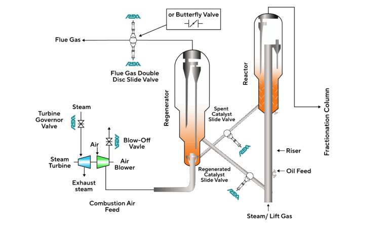
Fluid Catalytic Cracking (FCC) is an essential process in refineries used to convert heavy feedstock oil into valuable gasoline, jet fuel, diesel, and other products. During the FCC reaction coke builds up on the catalyst, limiting its ability to carry out the reaction. The spent catalyst is then transferred to the regenerator to burn off the residual coke. As the spent catalyst is regenerated, flue gas (combustion gas) is created by burning off residual coke. The flue gas must then pass through a valve which diverts it to a power recovery train or through a series of separators and electro-static precipitators before being released into the atmosphere.
Flue Gas Valve Purpose:
- Regulate the rate and direction of flue gas exiting the regenerator
- Helps maintain proper pressure differential between the regenerator and reactor
- Used for emergency isolation during upset conditions preventing backflow
Flue Gas Valve Configuration:
- Double disc slide valve to provide inherent redundancy
- Butterfly valve with additional redundancy applied to the actuator system
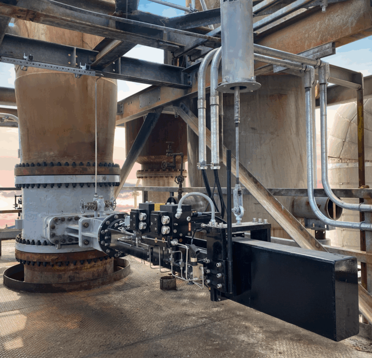
The key to success in this application is in engineering a Flue Gas Valve and actuator assembly that is capable of modulating with position accuracy, while providing fast signal response to control abnormal pressure disturbances. The Flue Gas exiting the regenerator has high pressure, high temperature, high volume, and will contain catalyst particulates. Tight control is critical in maintaining the FCC pressure balance in the cracking process. These conditions can require the Flue Gas Valve to be large in diameter necessitating the use of a hydraulic actuator often controlled by a Hydraulic Power Unit (HPU).
Problem
Poor Flue Gas Valve performance can create pressure unbalances, which can lead to an inefficient hydrocarbon cracking process. If this condition worsens, it creates potential for unplanned downtime and lost revenue. Common to all HPU systems is their inherent open loop design. Unlike other currently available hydraulic technologies, this design requires an intense maintenance program with frequent intervals. Atmospheric humidity makes contact with the hydraulic oil and creates acid build-up and premature oxidation. Additionally, dirt and particulate from the surrounding air enters the hydraulic system compounding the contamination issue. This is particularly problematic for servo and proportional valve driven hydraulic systems. These servo and proportional valve systems require very specific fluid cleanliness standards. If the fluid cleanliness comes out of spec, the system cannot perform as designed and will result in undesired inconsistent operation and the need to bring the system down for maintenance.
The effect of oil degradation requires an HPU to have several filters in the system that must be replaced frequently to effectively clean the oil. There are also dozens of soft goods within these systems that are subjected to high temperatures and need to be replaced periodically before they wear out and become potential leak paths. The pumps within these systems are constantly running to maintain a certain operating pressure for the hydraulic actuator to operate the valve. These continuously running pumps draw a lot of electricity and they must be maintained at a significant cost to ensure the valve and process stay online. Finally, HPU systems often have several hundred feet of hydraulic tubing and hoses which all represent potential leak paths. In order to prevent unscheduled unit downtime, HPU systems are placed on rigorous preventative maintenance programs which are time consuming and expensive.
Solution
Eliminate the risk of hydraulic oil breakdown, contamination, and maintenance by upgrading to REXA Electraulic™ Actuation. REXA self-contained actuators combine the simplicity of electric operation, the power of hydraulics, maximum reliability, and the flexibility of user-configured control. The principle behind REXA Electraulic™ Actuation is a unique hydraulic circuitry called the Flow Match Valve (FMV) system. The actuator incorporates a bi-directional gear pump coupled to a motor that provides a highly efficient method of pumping hydraulic fluid from one side of the double acting cylinder to the other. The motor and pump only move when a position change is required. Once the target position is reached, the motor and pump shut off and the FMV system hydraulically locks the actuator in place. Motor operation is not required to maintain actuator position; the motor and pump remain idle until a new command signal is received. This maximizes operation efficiency while minimizing wear and tear of the actuator itself. Additionally, the actuator can be configured with full redundancy of full critical components to provide maximum reliability and availability to get you from turnaround to turnaround (TAR).
Results
With REXA Electraulic™ Actuation the end-user gets all the performance advantages of a hydraulic actuator without the costly maintenance routine. The system provides immediate response to control signal changes and accurately modulates the position of the Flue Gas Valve to ensure efficient and safe process control.
- Eliminate the intense preventative maintenance routine of conventional HPU
- No more routine oil maintenance or fluid conditioning systems
- No more continuously running pumps wasting energy
- Achieve accurate Flue Gas Pressure Control with maximum reliability and operational safety
- Enable stable regenerator pressure with steady differential pressure between the reactor and regenerator
Installing a REXA actuator on your Flue Gas Valve allows you to get better control of your FCC process!
Literature
Download the full Fluid Catalytic Cracking Flue Gas Pressure Control Application Spotlight here!